Important: fully read through this entire manual first before starting the battery replacement!
Tools required:
- two high quality CR2032 batteries (do not use cheap Chinese rubbish)
- Size 8 torx screwdriver
- Soldering iron, solder & flux
- Spudger, pen knife or flat blade screwdriver
- Short length of thin automotive cable
- 40 cm piece of string
- Gaffer tape
- small piece of soft foam
- Torque wrench
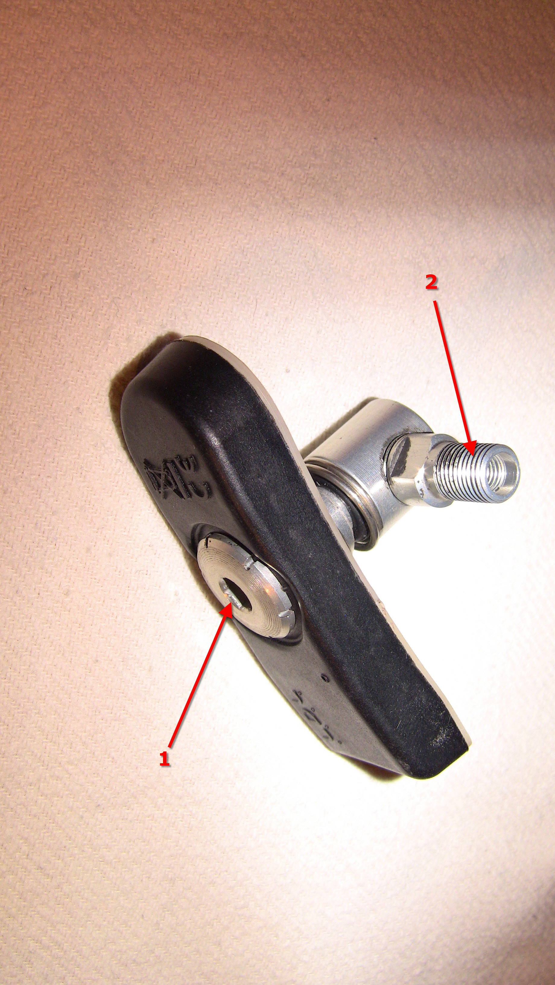
Here is an image of an LDL TPMS sensor after removal from the rim:
Remove the bolted-on valve stem (2) by turning it counter-clockwise. You may have to hold the hex head of the bolt (1) on the opposite side of the unit to prevent it from spinning.

Remove the pressure spring (3). Remove the single torx bolt (4) that keeps the backplate (5) of the sensor in place.
Carefully pry the backplate loose. It is clamp-fitted onto the central hex bolt (6) and clip-fitted onto the main sensor body. Careful prying should get it off the main sensor body without requiring any tools. Do not yet try to remove the backplate from the central hex bolt.
Once the backplate is off, then turn it counter-clockwise as in this image:

Continue turning the backplate until you can remove the the backplate from the hex bolt without using any force:
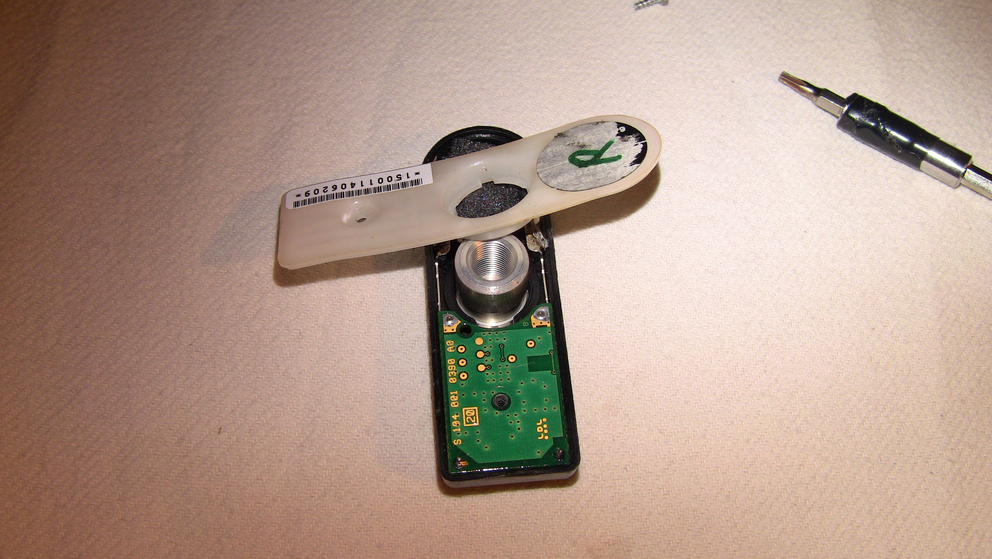
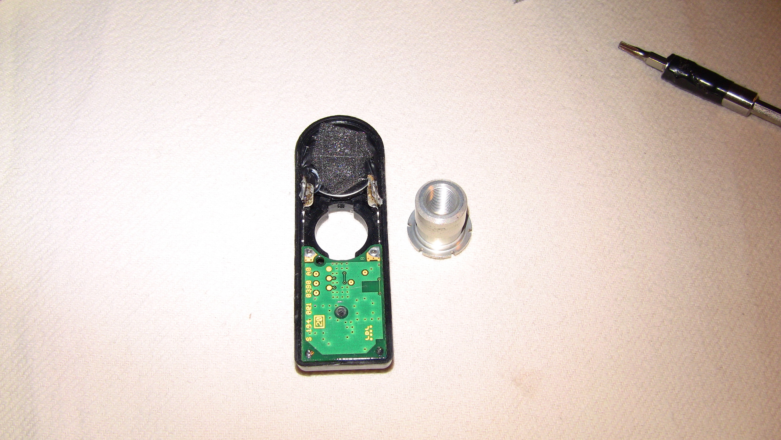
The hex bolt can now be removed from the main sensor body:
There may be a tiny rubber-type pad glued onto the inside of the backplate, designed to put some pressure onto the sensor battery to keep it in place. If present, remove and discard the pad. We won‘t need it any more.
The images in this manual show the sensor with all my modifications already made (I didn‘t have an original sensor available).
If this is the first time that you change the sensor batteries, then you will find that the sensor battery is soldered into place with two flat metal foil strips (they are about 12 – 15 mm long) which connect the battery to the metal flanges extending from the main board.
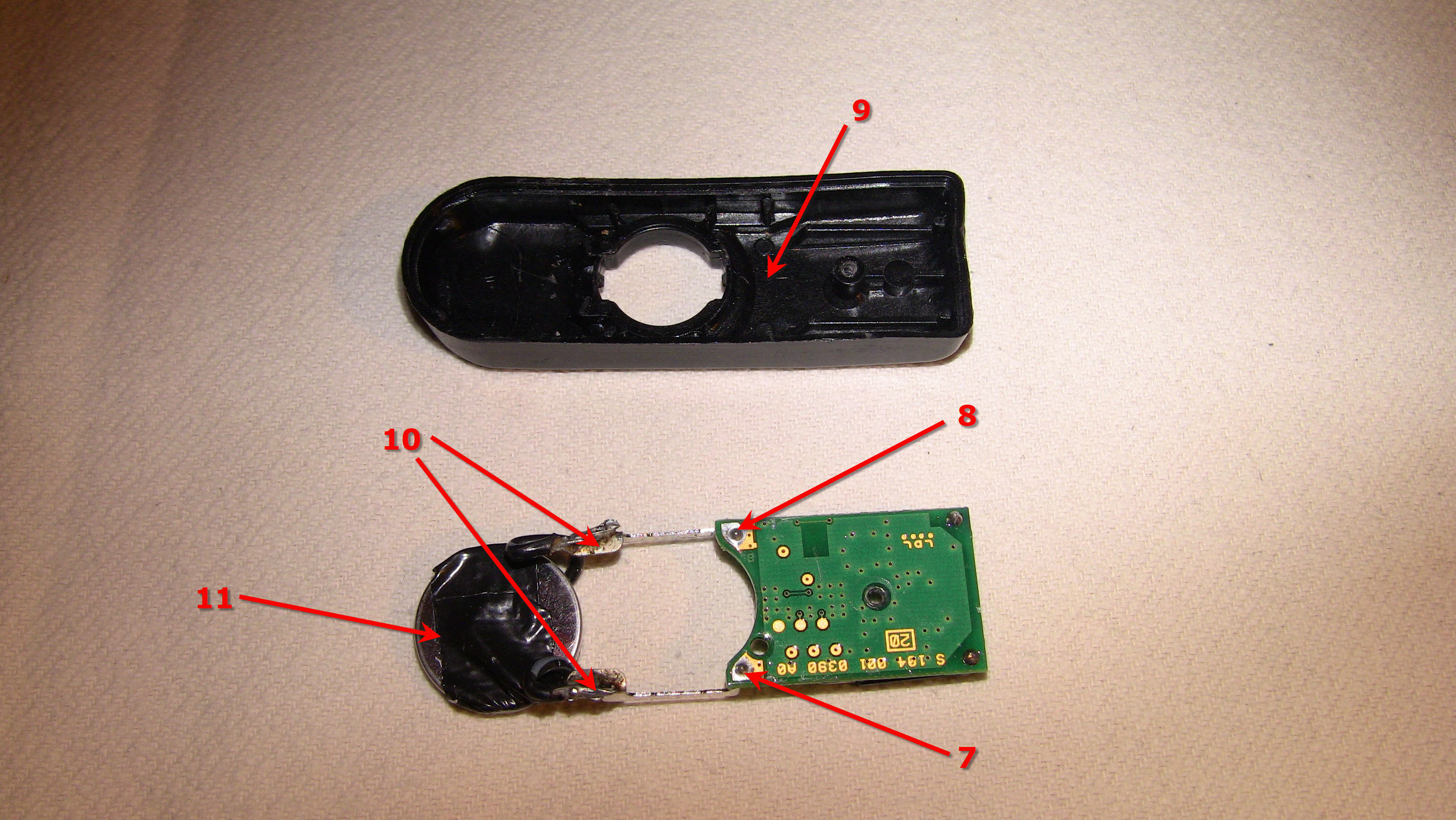
Carefully pry the main circuit board and the battery out of the housing like in this picture:
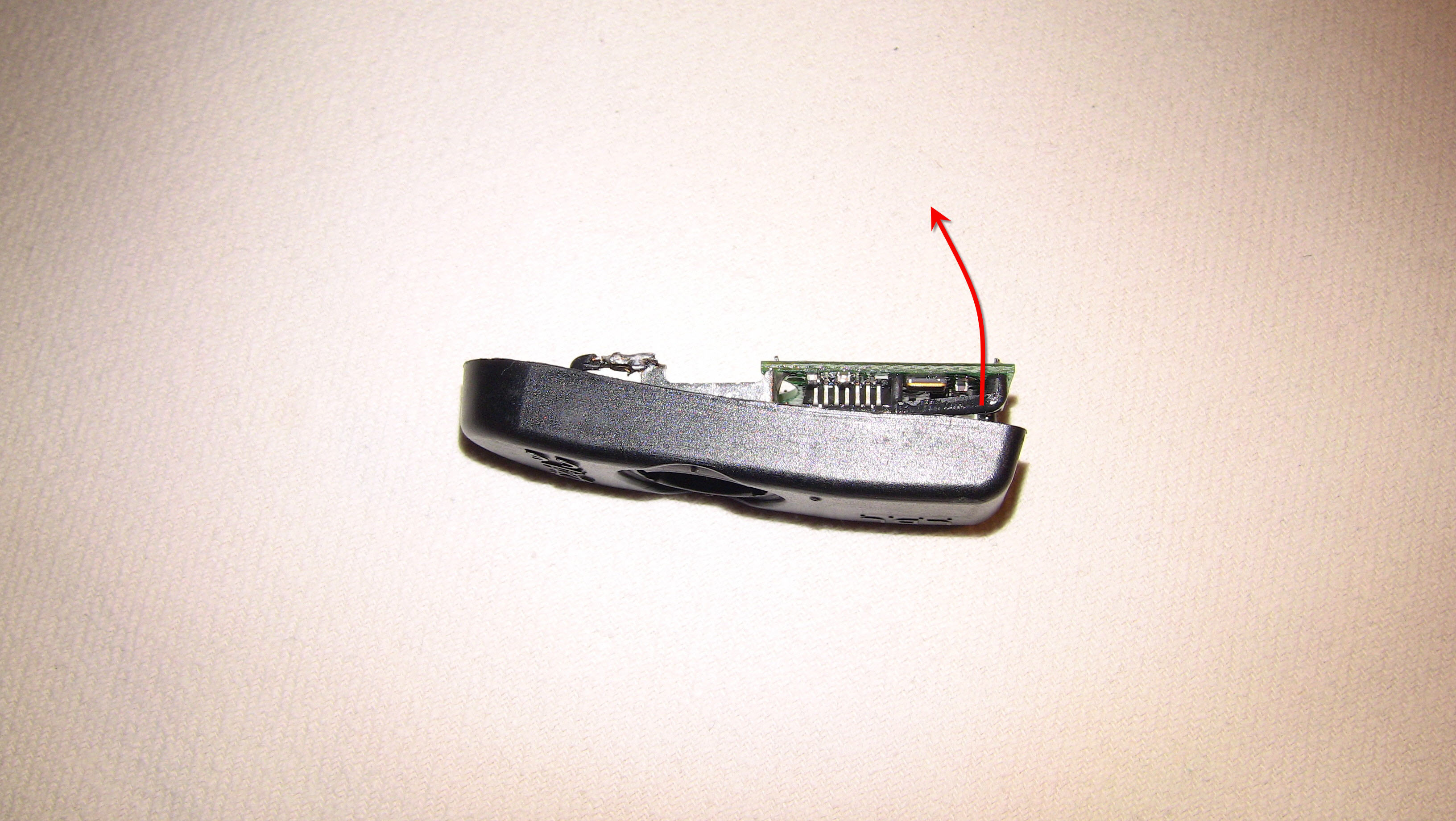
It may be necessary to insert a small, flat-bladed screwdriver or a spudger under the board to pry it off. Be very careful not to damage any of the sensitive electronic components on the board.
De-solder the remainder of the original metal foil strips (if this is the first time you replace the batteries) which connect the old battery to the two metal power connector bars that extend from the main circuit board.
Solder a short piece of thin automotive cable (about 25 mm long) onto each end of the metal power connector bars (10) as replacements for the original metal foil strips (see images below).
Remove about 8mm of cable insulation from the battery side of the soldered-on cables, ensuring that they will have ample connectivity to the replacement battery:
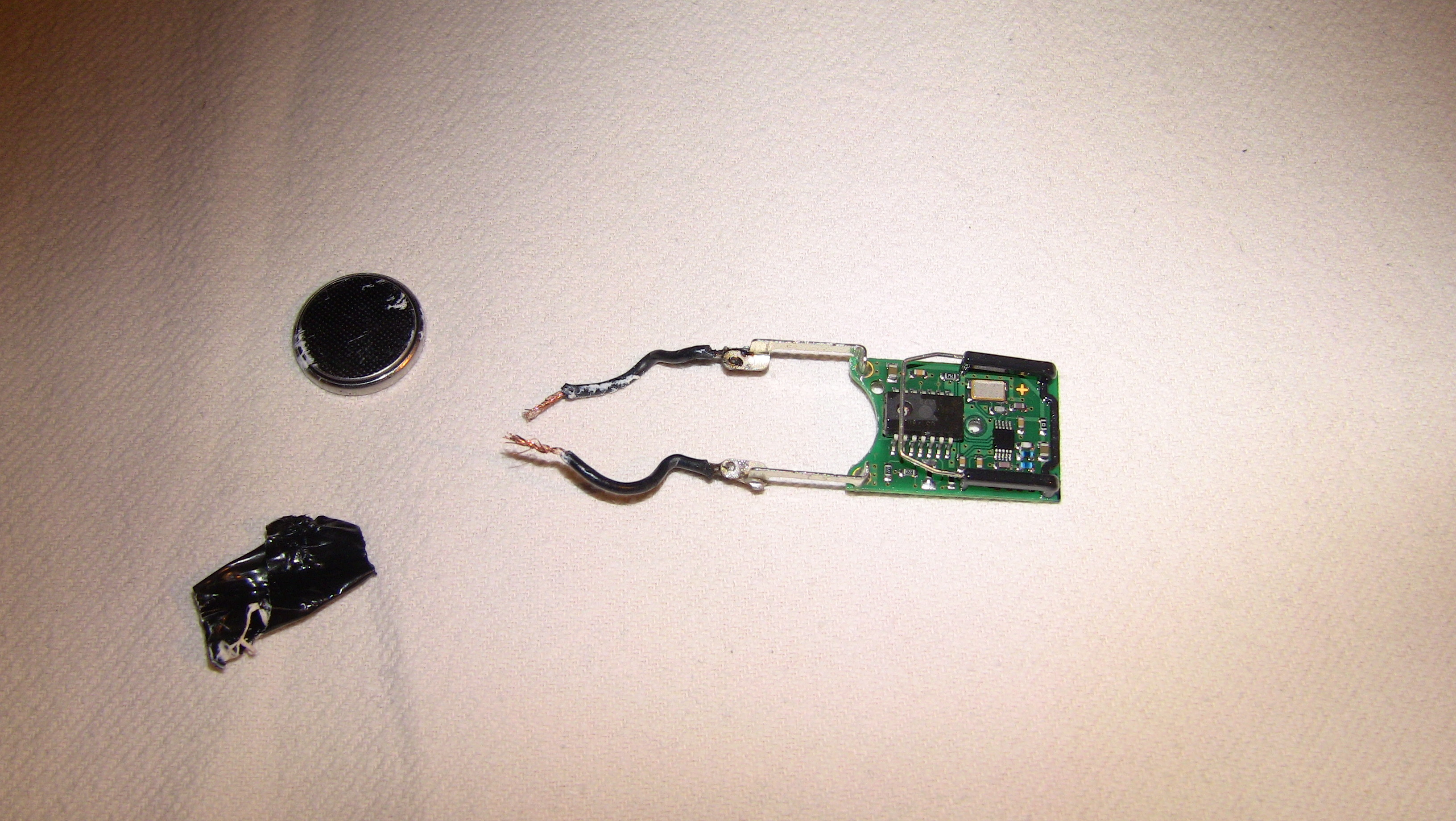
Connect the cable ends to a new CR2032 type battery using Gaffer tape. Make sure that the two soldered-on cables have a good connection to the new battery.
Note the cable polarity above in image 7 – if you inverse the polarity (i. e. connect the battery the wrong way round) you may destroy the sensor.
The polarity of the new CR2032 battery is clearly etched onto the battery housing.
Carefully insert the taped-up battery back into the sensor housing, but do not yet insert the main board into its correct location in the housing.
Only once the battery is properly seated should you insert the main board back into the housing. Make sure that the solder points do not touch or shorten out the battery.
If you accidentally shorten out the new battery, then the battery immediately becomes unusable. In that case, replace the battery for a new one. The new battery should have a voltage of about 3.3 volts if it is good.
Before putting the backplate into its position on the main housing, place a small piece of soft foam on top of the battery (about 15mm in diameter and 10 mm thick when uncompressed) to make the backplate put some pressure on the battery to keep it properly in place.
Re-fit the rest of the sensor components in the reverse order of disassembly.
If the backplate does no longer fit flush onto the main sensor body, then you can affix it using a small piece of gaffer tape.
Attach a piece of string of about 30 – 40 cm length to the neck of the valve around the spring that puts pressure on the valve stem.
Switch on the receiver unit (if OEM LDL receiver is used) or the motorbike's ignition (if built-in display is used), then start swinging/rotating the sensor on the end of the string to apply centrifugal force to it to activate the sensor. Make sure that the valve is on the inside of the swing circle, similar to how it is located when the sensor is properly fitted on a wheel.
If the new battery is properly fitted, then the receiver unit should change the shown value from „--.-“ bar to „0.0“ bar, indicating that the sensor is reporting zero air pressure. The red „low pressure“ LED or tyre pressure warning light on the bike‘s display might come on, too, if the receiver was configured to report low pressure via that LED or the display warning light.
This means that the sensor is working fine with the new battery and can now be fitted into the motorbike‘s rim.
Re-fit the sensor into the rim of the bike, ensuring that you tighten the valve stem to the torque recommended by LDL (at the time of writing this manual this was 4.2 Nm +/- 0.2 Nm)
Here is a PDF manual from LDL that shows the function of the LDL Tyre Watch product.
And here is the PDF sensor mounting manual for tyre dealers from LDL that shows how to correctly install and torque the sensors.