Why should I fit a BoosterPlug? You can find a detailed technical function description here, but in short it will overcome the problem that like most other modern engines the Triumph engines run on too lean a mixture. This causes the much lamented brutal throttle opening response, i. e. when accelerating out of a curve. This behaviour will be practically eliminated by the Plug. It achieves this by tricking the ECU into thinking that it is 20 degrees cooler than it actually is, causing an increase of fuel in the fuel/air mixture that reaches the engine by about 6 percent.
"Why shouldn't I just connect my laptop to the ECU with TuneECU and set the mixture over the entire map richer by six percent?" you may now ask. Well, people have done this and it worked like a treat. What I don't like about that solution is the fact that this also causes the fuel consumption to increase by six percent. The Plug only acts when the throttle position changes (see above link to the main technical page if you want to know why), but when riding with a fixed throttle position (i.e. on a long country road at constant speed) the Plug is ignored by the ECU. As a result the fuel consumption increase is marginal when using the BoosterPlug. The price of the BoosterPlug will pay for itself - compared to setting the ECU mapping six percent richer - over 20000 km in saved fuel expenses. For me that is in less than a year.
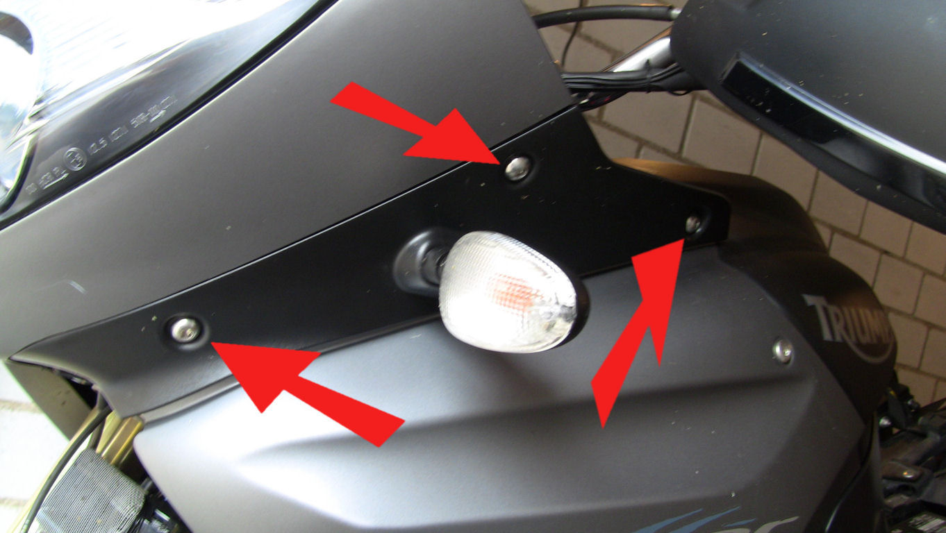
So let's begin the work. Start by removing the three bolts that keep the indicator mount on the bike:
Remove the indicator unit. Do the same work on the indicator unit on the right side. Next remove these three bolts and remove the side panel:
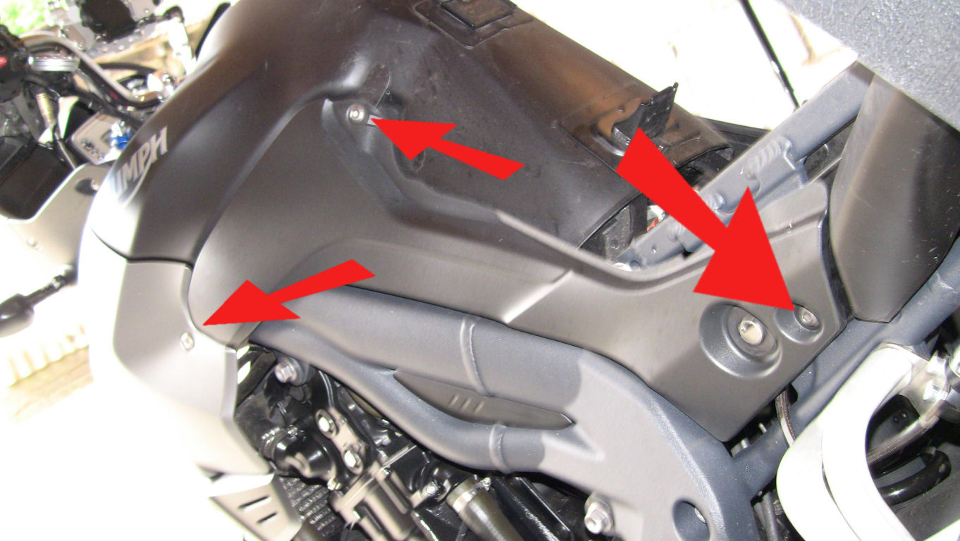
Do the same for the side panel on the right side of the bike. Next remove this bolt...
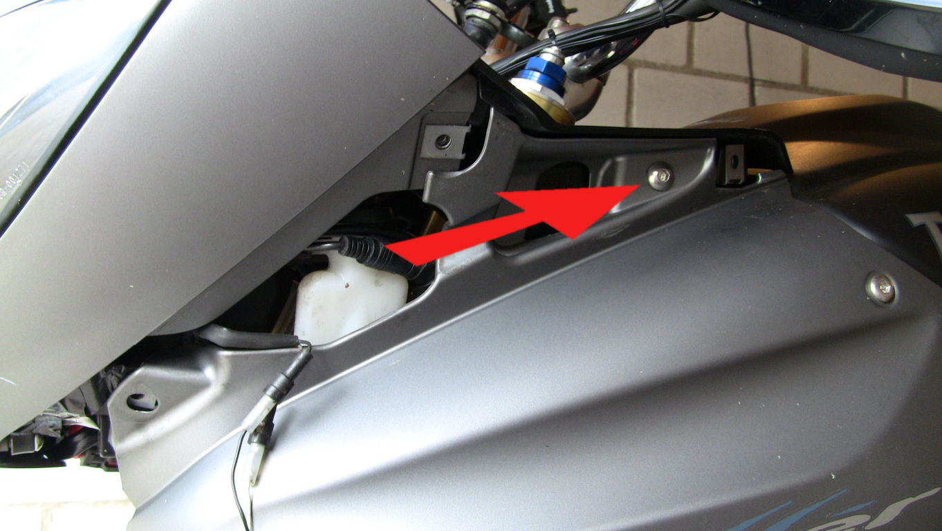
...and then pry off the cockpit cover panel.
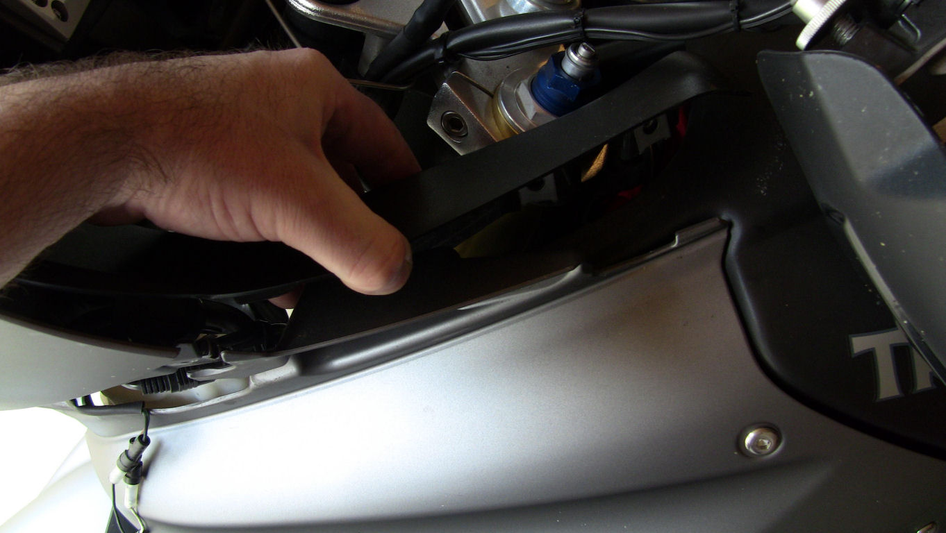
Do the same for the panel cover on the right side of the bike. Now remove these two bolts:
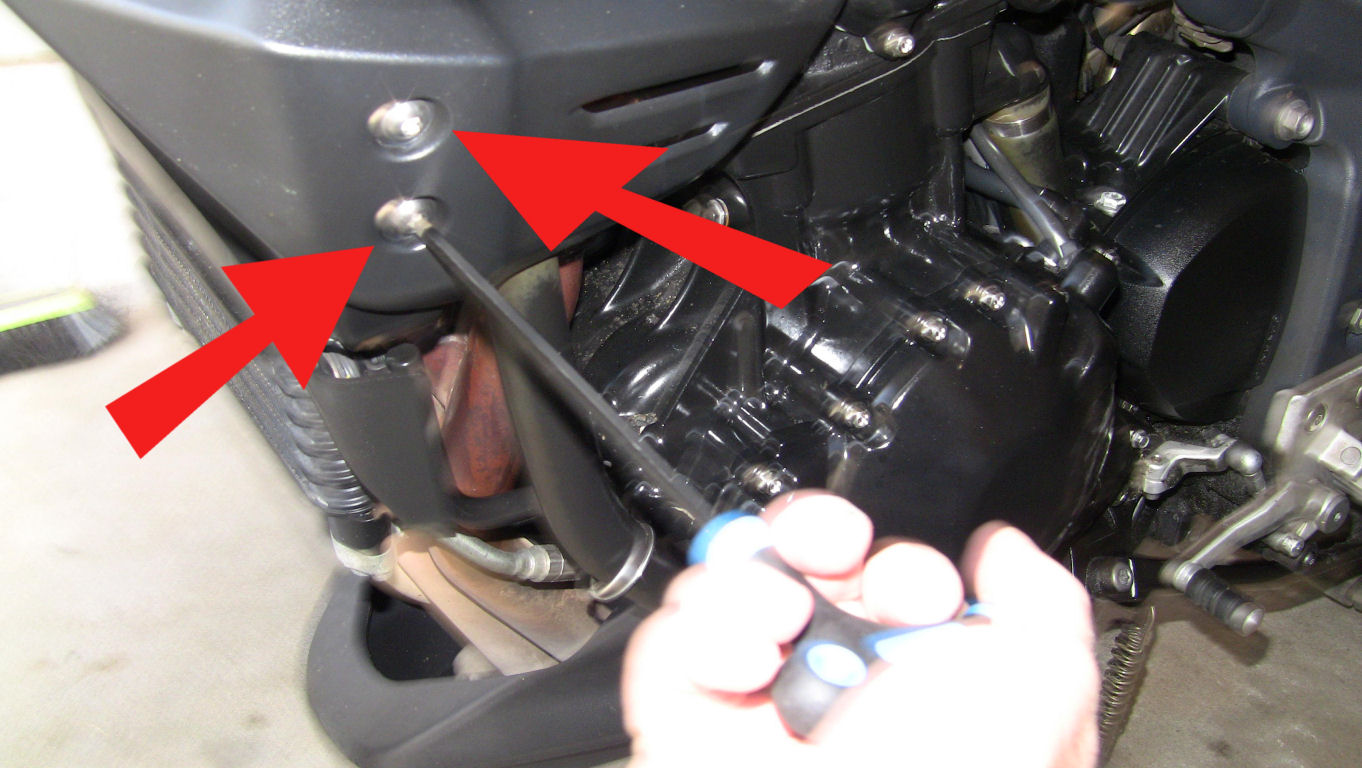
Take off the side panel the bolts were holding in place. Do the same for the side panel on the right side
of the bike.
Next remove the remaining bolt on the main tank cover and take the cover off:
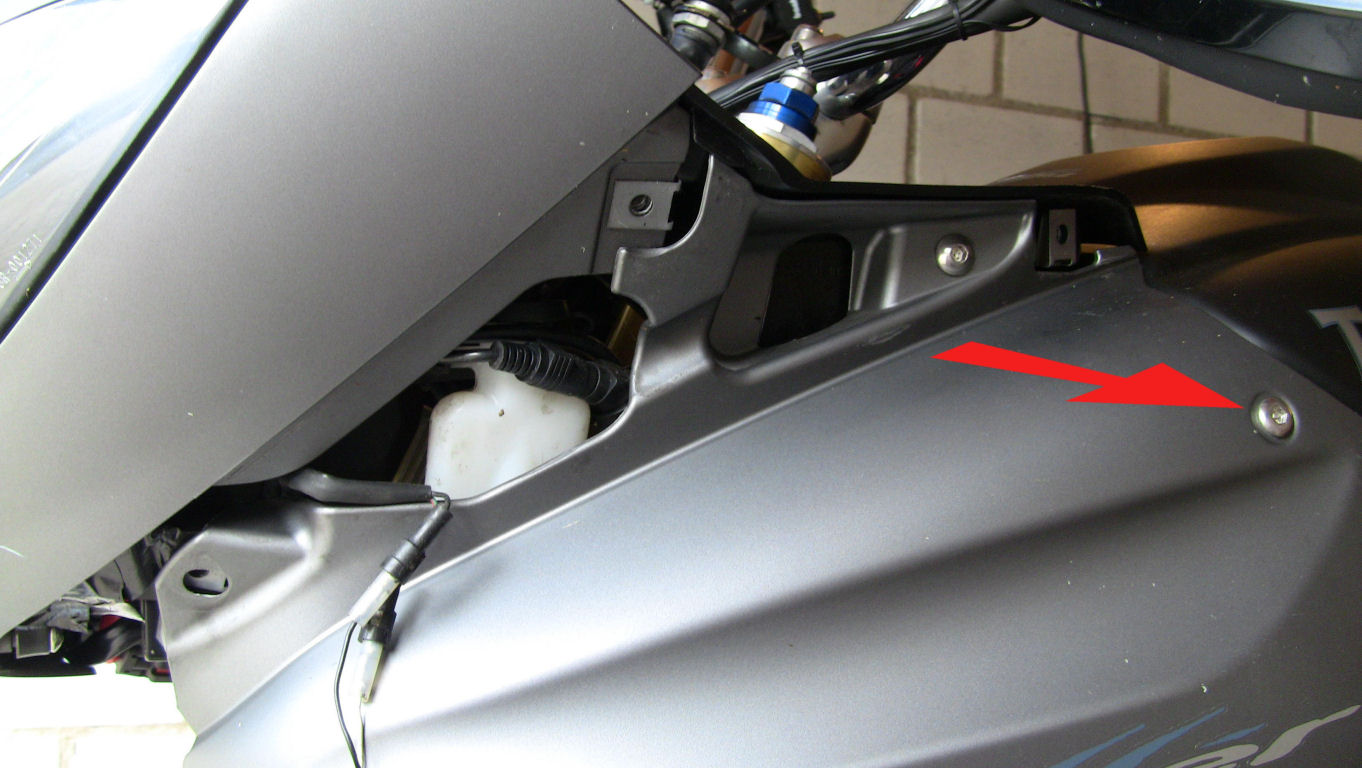
Do the same for the
cover on the right side of the bike.
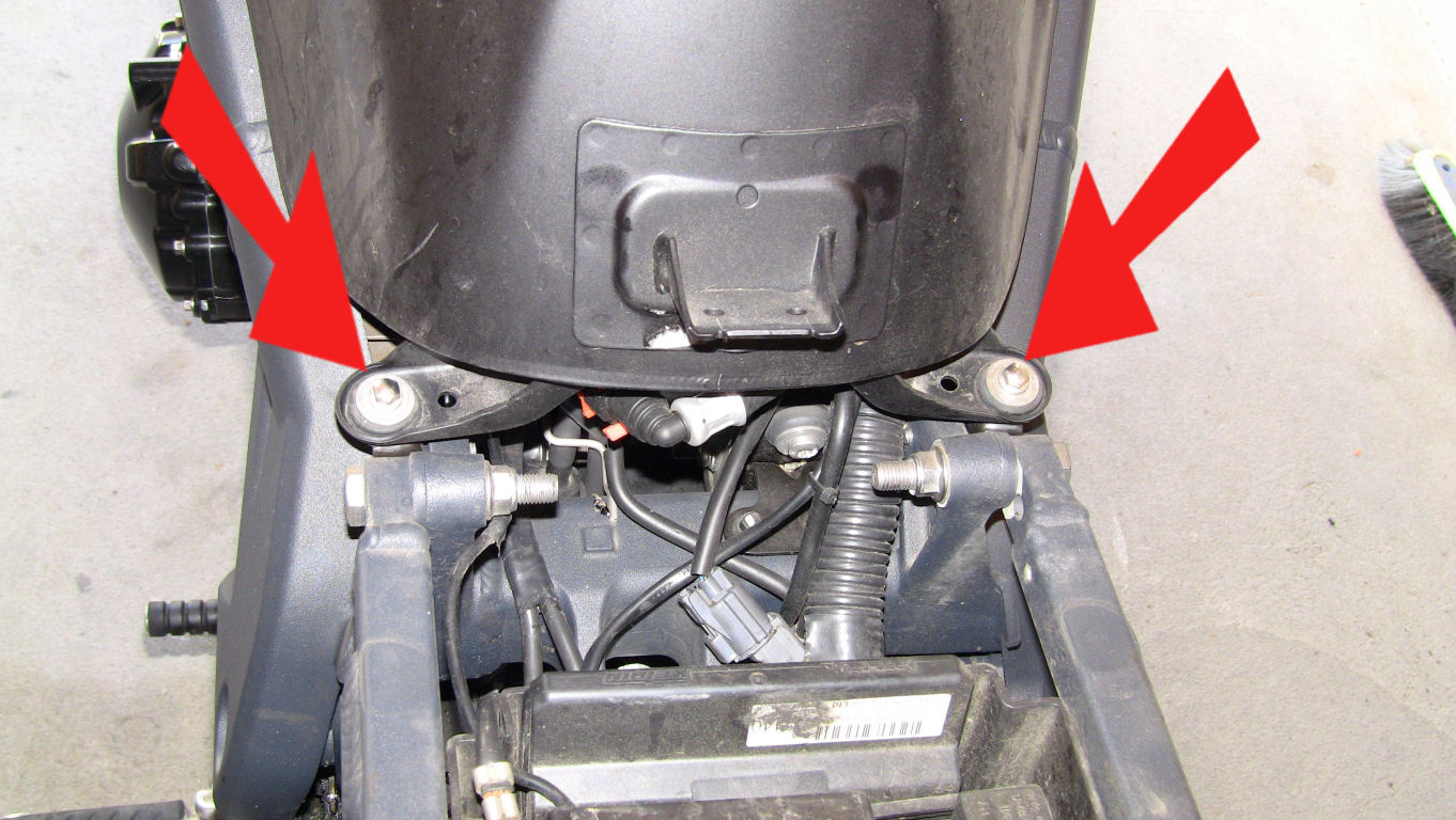
Now remove the two bolts securing the tank at the rear:
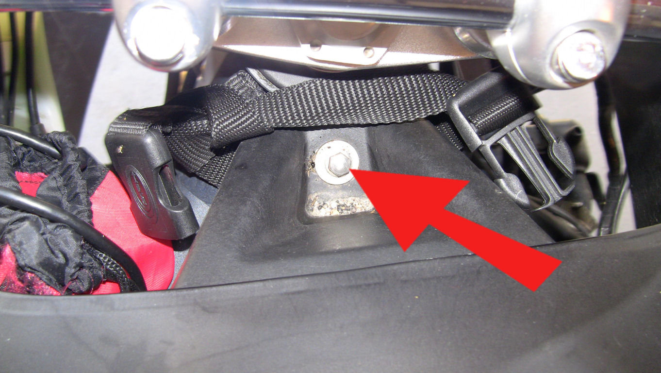
Next remove the bolt securing the tank up front next to the steering head. Ignore those straps you see in below image, they belong to my tank bag:
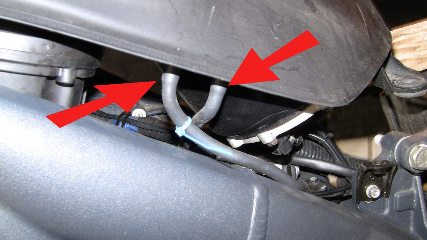
Prop up the rear end of the tank using a bit of wood so that you can get at the connectors. First disconnect the breather pipes on the left side of the tank marked in below picture. Note that I have marked the front pipe with a blue cable tie so that I know which one belongs onto which connector on reassembly.
Next unplug the black and the brown cable connectors:
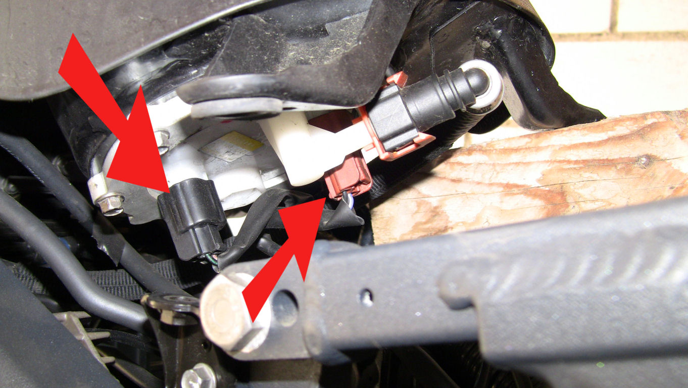
Now the fuel pipe must come off. Have a rag at hand, as a few drops of fuel may spill out. The connector is self-sealing, so there shouldn't be more than a few drops coming out when disconnecting it.
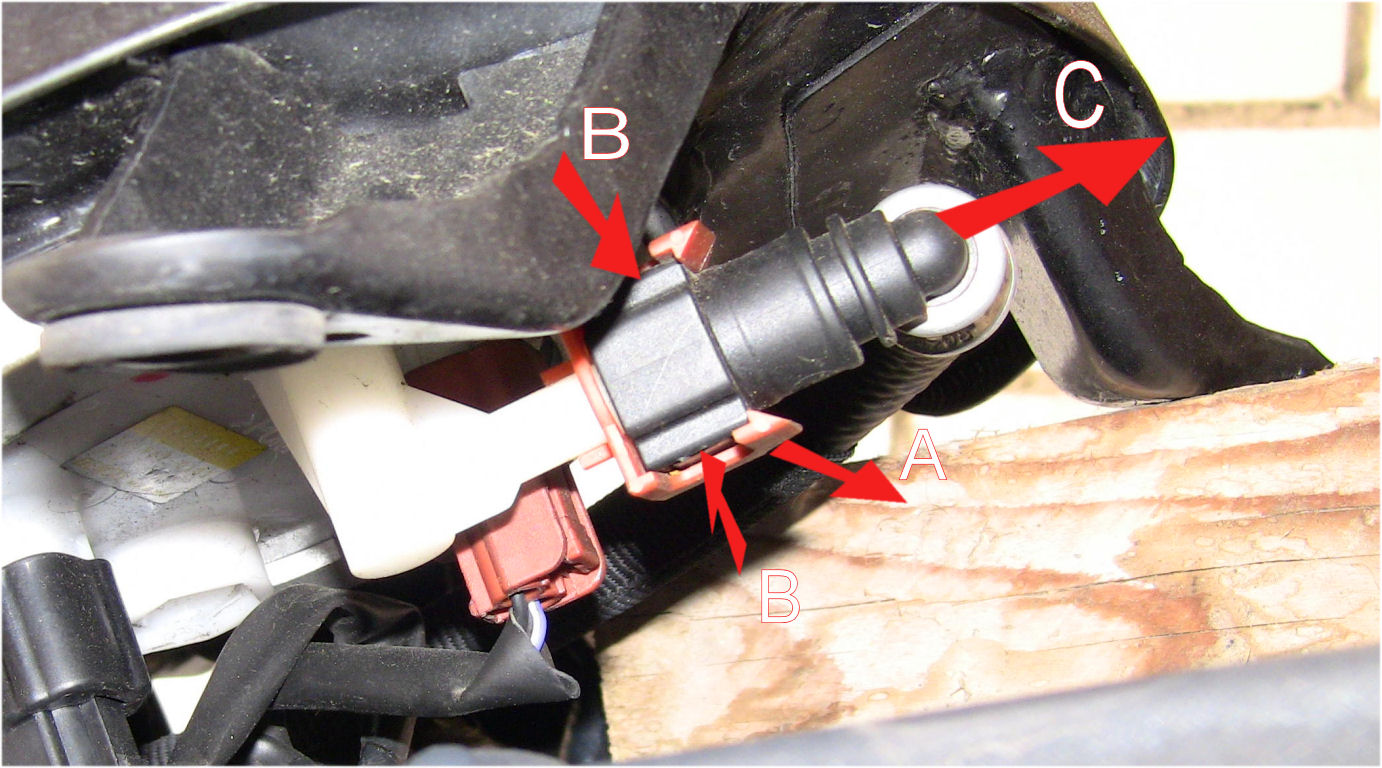
First push the brown plastic clip backwards (A), then squeeze the now visible sides of the connector with two fingers (B). You should feel when they move. Do not use force or the unit may break. Pull the black fuel pipe unit off the white connector pipe (C).
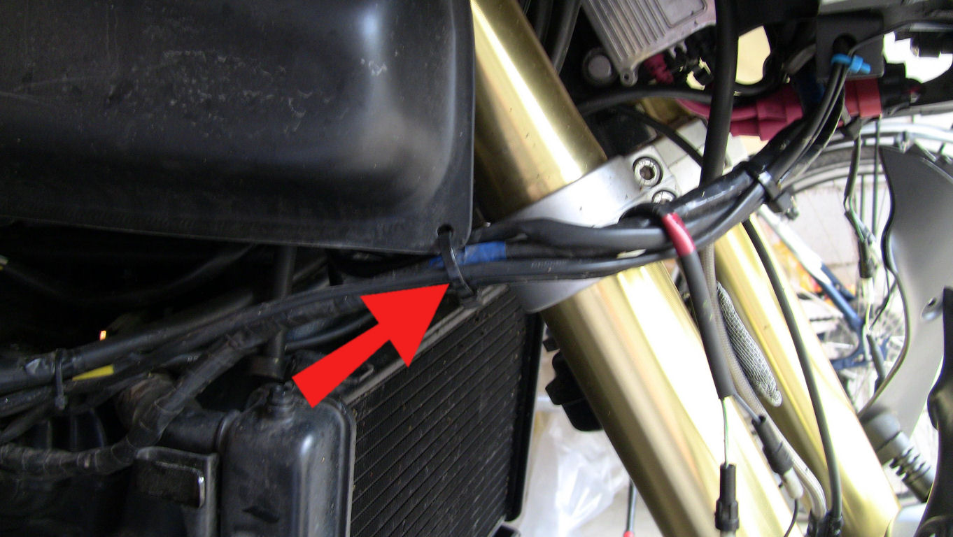
On the front right side of the tank, cut the cable tie that keeps the wires on place. I have some extra electronics (Nav, coms, HID's etc.) on my bike, so you probably find that the cable tie on your bike carries less cables.
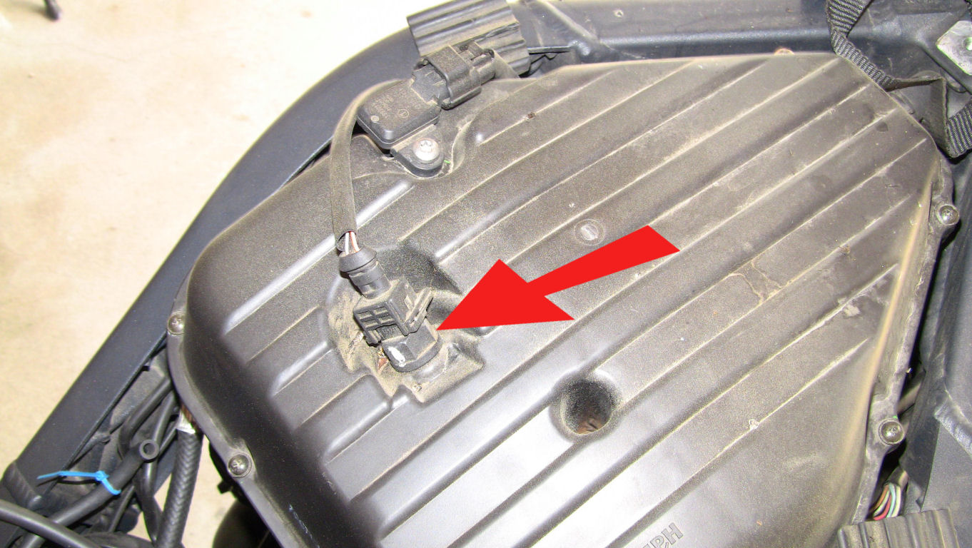
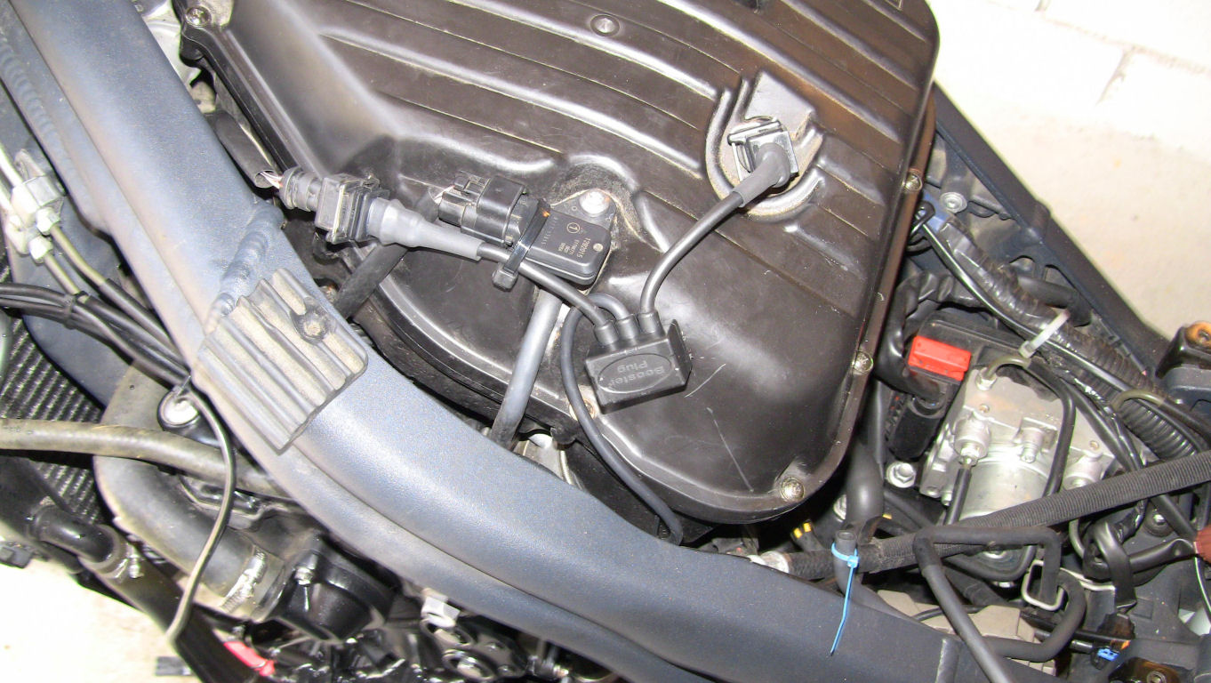
Now you can lift the tank from the bike. Underneath it is the air filter housing. You will find the air intake temperature sensor on top of it, marked in this picture:
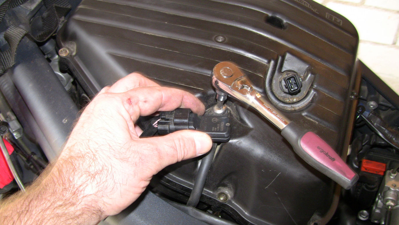
The other sensor above it is the manifold pressure sensor. You can either disconnect the cable and the pressure pipe from the manifold pressure sensor or unbolt the Torx bolt keeping it in place and put the entire unit to one side. Secure the sensor unit when unbolting with one hand to prevent it from slipping against (and cracking on) the air-filter housing:
You can now undo the eleven bolts that keep the upper air filter cover in place. The eleventh bolt is hidden in that little hole in the cover you can see above the air temperature sensor in above picture. Remove the air filter cover and the air filter element. Place a protective rag over the three throttle body air intakes to prevent any foreign object from falling into them. This is what you should see:
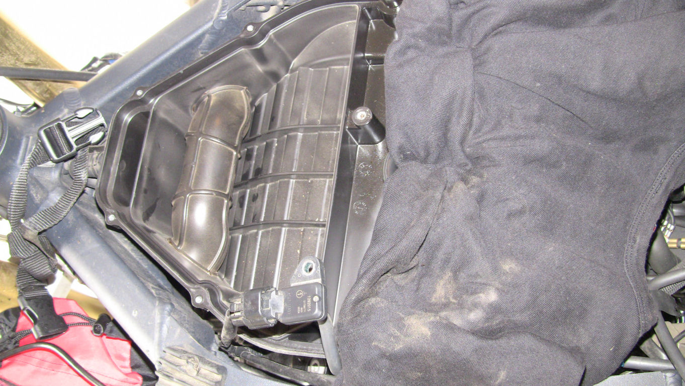
Lot's of people have fitted the temperature sensor of the BoosterPlug somewhere under the seat or under the dashboard. The air intake of the Tiger 1050 is placed directly over the radiator, so this might lead to misreadings, resulting in incorrect fuel/air mixture ratios. Triumph did place the air temperature sensor for a reason inside the air filter housing, so we do the same. Here is my solution:
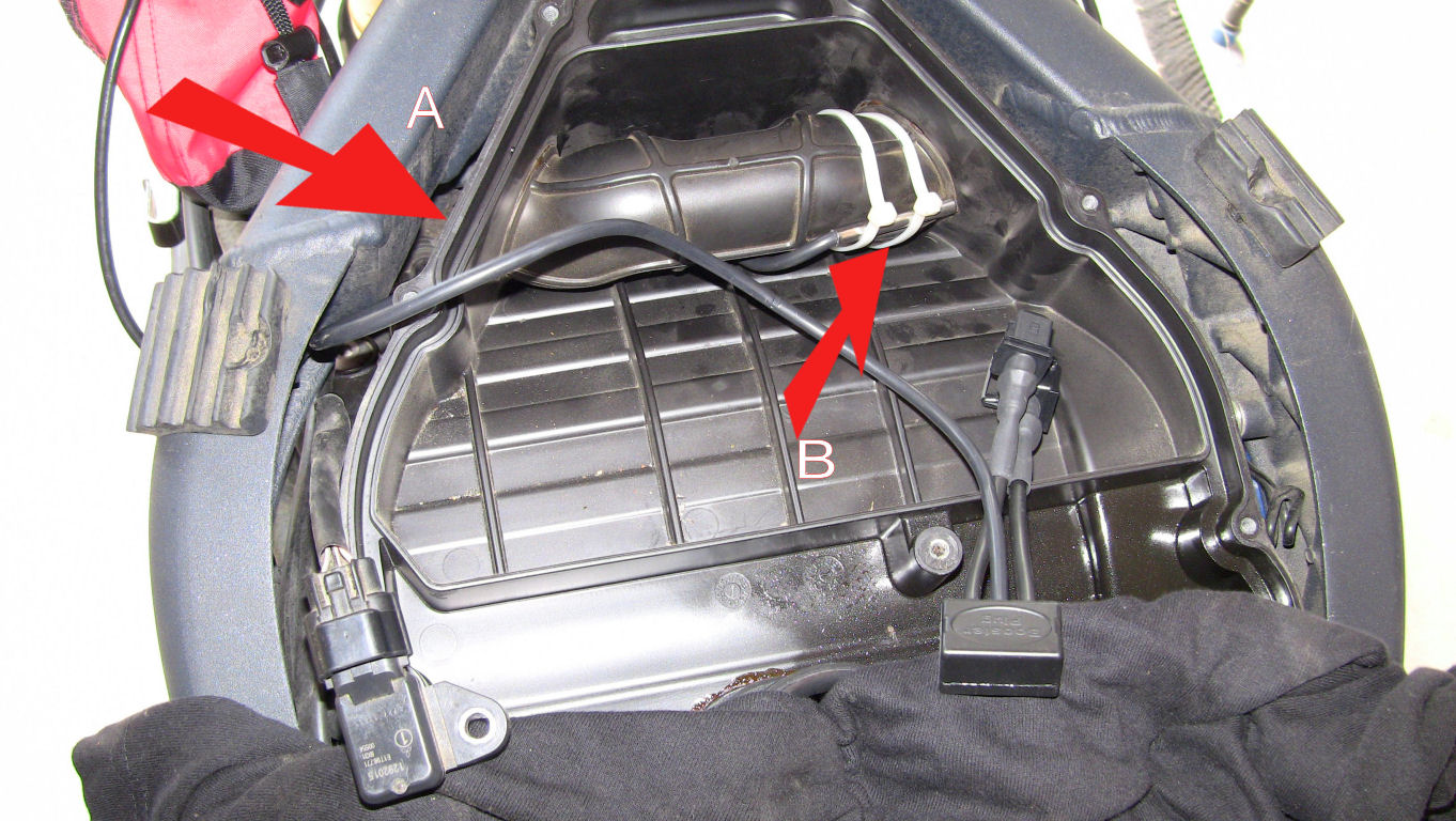
The cable is routed through the air inlet (A) and the sensor then strapped with two cable ties to the rubber air bridge (B). Now re-fit the air filter element and the filter housing cover. The cable from the BoosterPlug to the air temperature sensor is rather short (though one can easily extend it by just cutting it and soldering some more cable in). After some experimenting I have found a position for the Plug and the cabling that does not interfere with the tank and will not require extending any cables:
I placed the Plug itself in position with a Velcro-pad. I have ABS on my bike, and the ABS brake piping gives a solid base for routing the cables along using cable ties.
Refit the rest of the parts previously removed back to the bike. Refitting is the reverse of the dis-assembly. Note the position of the two rubber protectors which support the tank (you can see the left one in above image) and make sure they are correctly positioned.